How to Upgrade Wear-Prone Elbows, Tees, and Pump Discharge Sections with Localized Pipeline Replacement
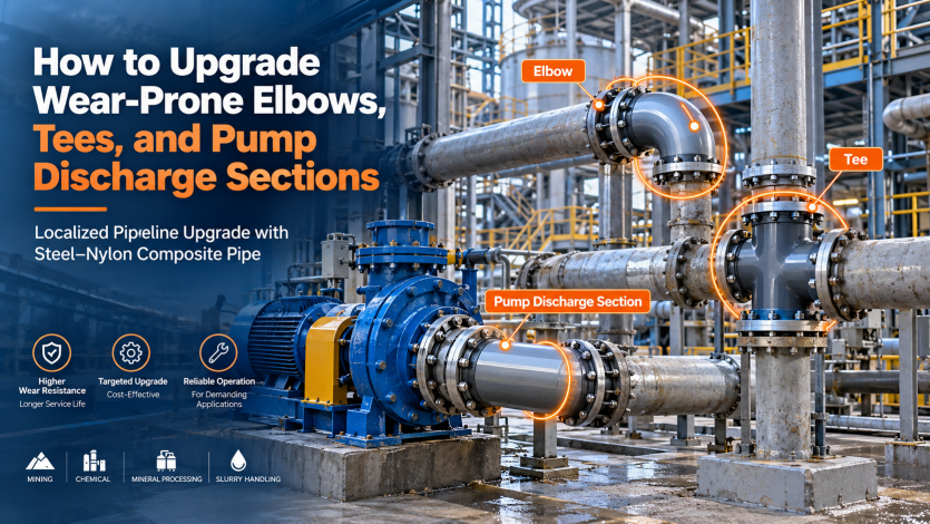
In slurry transportation, tailings pipelines, chemical mother liquor systems, brine service, oilfield produced water lines, and high-solids slurry systems, one phenomenon is particularly common:
The entire pipeline rarely reaches the end of its service life at the same time. The components that fail most frequently are usually a limited number of critical sections.
Typical examples include:
-
90° elbows and large-angle bends;
-
Tees at flow splitting or merging points;
-
The first straight pipe and elbow downstream of a pump discharge;
-
High-velocity erosion zones downstream of valves;
-
Reducers and sudden diameter transitions;
-
Sections involving significant elevation changes;
-
Locations where the direction of slurry flow changes rapidly.
These sections may account for less than 5% of the total pipeline length, yet they can be responsible for a disproportionately high share of wear, leakage, maintenance, and unplanned shutdowns.
For mines, chemical plants, and oilfield pipeline systems already in operation, upgrading the pipeline does not necessarily mean:
“Removing and replacing the entire pipeline.”
In many cases, a more economical strategy is to:
Identify areas subject to severe wear, corrosion, and impact, and selectively upgrade those sections with steel–nylon composite pipe.
This approach can be described as:
Localized Pipeline Upgrade.
The objective is not to use exactly the same material throughout the entire pipeline, but to select materials according to the actual failure mechanism at different locations.
1. Why Do Elbows Often Fail Earlier Than Straight Pipe?
In pipelines carrying clean water or low-solids fluids, the difference in wear between straight pipe and elbows may not be significant.
However, the situation changes dramatically when the transported medium contains:
-
Mineral particles;
-
Tailings;
-
Iron ore fines;
-
Limestone slurry;
-
Salt crystals;
-
Catalyst particles;
-
Suspended solids;
-
Corrosive crystalline particles.
In straight pipe, solid particles generally travel in the axial direction.
When the flow enters an elbow, however, the particles cannot immediately follow the curved fluid streamline because of their inertia.
As a result, a large proportion of the particles impact the:
Outer radius of the elbow.
An elbow can therefore be exposed simultaneously to three different damage mechanisms.
1.1 Impact Erosion
High-velocity particles repeatedly strike the pipe wall, gradually cutting and removing material from the surface.
1.2 Sliding Abrasion
Solid particles slide along the inner surface of the elbow, producing continuous abrasive wear.
1.3 Synergistic Corrosion and Wear
When the transported medium is also corrosive, such as:
-
High-salinity water;
-
Acidic mother liquor;
-
Alkaline solutions;
-
Chloride-containing fluids;
-
Produced water containing CO₂ or H₂S;
the protective film on a metallic pipe surface may be repeatedly damaged by solid particles.
Fresh metal is then exposed to the corrosive medium, creating a repeating cycle:
Corrosion → Protective Film Damage → Wear → Fresh Metal Exposure → Further Corrosion
This is one of the reasons conventional steel elbows can experience much shorter service lives than straight pipe sections in certain operating conditions.
2. Why Are Tees Another Common Weak Point?
The failure mechanism of a tee differs from that of a conventional elbow.
At a tee, fluid flow may experience:
-
Flow splitting;
-
Flow merging;
-
Direct impact;
-
Recirculation;
-
Secondary flow;
-
Local pressure fluctuations.
In high-velocity slurry systems, if the slurry directly impacts the wall opposite the branch connection, severe:
Impingement Erosion
can occur.
For example, in a T-shaped fitting, slurry can strike the opposite wall before changing direction.
The localized wear rate at the impact surface can therefore be much higher than in an ordinary straight pipe.
A common operating situation is:
“The straight pipe is still usable, but the tee has already worn through.”
If the entire production line must be stopped whenever a tee fails, the purchase price of the tee itself may be relatively insignificant.
The real cost is:
Production downtime.
3. Why Is the First Pipeline Section After a Pump Particularly Vulnerable?
Many industrial operators find that the first section downstream of a pump discharge experiences more severe wear than pipeline sections farther away from the pump station.
One important reason is that the pump discharge area usually experiences higher:
-
Flow velocity;
-
Turbulence intensity;
-
Pressure fluctuations;
-
Particle kinetic energy;
-
Localized impact forces.
This problem becomes even more significant when a centrifugal pump outlet is immediately connected to:
-
A 90° elbow;
-
A reducer;
-
A valve;
-
A tee.
These components can create highly complex local flow conditions.
For high-solids slurry systems, the result can be a combination of:
High-Velocity Particle Impact + Turbulence + Pressure + Corrosion
Therefore, pump discharge sections should be treated as critical areas in wear-resistant pipeline design.
4. The Real Question Is Not “Which Pipe Is the Most Wear Resistant?” but “Where Does the Wear Occur?”
Many industrial pipeline systems are still designed according to a traditional concept:
Use the same material throughout the entire pipeline.
For example, an entire line may be constructed using conventional carbon steel.
When localized wear becomes severe, the damaged pipe section is replaced with the same material again.
The major weakness of this strategy is that:
Wear is rarely distributed evenly throughout an industrial pipeline system.
In many slurry transportation systems, the relative failure risk may look like this:
| Pipeline Location | Relative Failure Risk |
|---|---|
| Long straight pipe sections | Medium |
| Small-angle bends | Medium |
| 90° elbows | High |
| Tees | Very High |
| Pump discharge sections | Very High |
| Downstream of valves | High |
| Reducers | High |
This means that only part of the system may actually require a higher-performance material.
A more rational engineering strategy is therefore:
Select pipeline materials according to localized failure risk.
5. What Is a Localized Pipeline Upgrade?
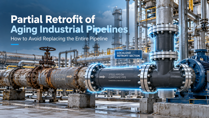
A localized pipeline upgrade means retaining existing pipeline sections that still have sufficient remaining service life while replacing only high-risk sections with improved materials.
For example, consider a 2,000-meter slurry pipeline where the majority of severe wear is concentrated in:
-
Eight 90° elbows;
-
Four tees;
-
Two pump discharge sections;
-
Six reducer sections.
Instead of immediately replacing the entire 2,000-meter pipeline, these critical locations can be upgraded first.
The basic logic of localized upgrading can be summarized as:
Identify → Prioritize → Replace → Monitor
In other words:
Identify failure locations → Prioritize high-risk areas → Replace critical sections → Continuously monitor performance
This approach is particularly suitable for:
-
Aging pipelines that have already been operating for many years;
-
Systems experiencing repeated localized leakage;
-
Production plants with high shutdown costs;
-
Projects where complete pipeline replacement is not immediately practical;
-
Customers wishing to validate a new pipeline material before wider adoption.
6. Why Is Steel–Nylon Composite Pipe Suitable for Localized High-Risk Sections?
Steel–nylon composite pipe is not simply a steel pipe with an ordinary plastic liner.
Its engineering concept is based on:
Using different materials to perform different functions.
The steel structure primarily provides:
Mechanical strength and pressure resistance.
The enhanced nylon functional layer primarily provides:
Wear resistance, corrosion resistance, and separation of the transported medium from the metallic structure.
This combination can be particularly valuable for elbows, tees, and pump discharge sections.
7. Steel Structure for Mechanical Strength
In mining slurry systems, oilfield gathering systems, and chemical transportation pipelines, customers are not only concerned about abrasion resistance.
They must also consider:
-
Operating pressure;
-
Water hammer;
-
Structural loads;
-
External impact;
-
Flanged connections;
-
Structural stability of large-diameter pipelines.
Purely flexible non-metallic materials may not be appropriate for every operating condition.
A steel–nylon composite structure retains the mechanical support provided by steel and is therefore particularly suitable for applications requiring a combination of:
Wear Resistance + Corrosion Resistance + Pressure Capability
8. How Can the Enhanced Nylon Layer Reduce Particle Erosion?
Wear resistance is not determined by material hardness alone.
Actual slurry erosion is influenced by many factors, including:
-
Particle hardness;
-
Particle size;
-
Flow velocity;
-
Impact angle;
-
Material toughness;
-
Surface friction characteristics.
In areas exposed to repeated particle impact, excessively brittle materials can develop:
-
Microcracks;
-
Surface spalling;
-
Fatigue damage.
Enhanced nylon materials provide a degree of toughness and impact resistance, allowing them to absorb part of the energy generated by repeated particle impact.
This characteristic can be particularly valuable at:
-
The outer radius of elbows;
-
Tee impact surfaces;
-
Pump discharge sections;
-
High-velocity slurry zones.
9. Reducing the Synergistic Effects of Corrosion and Wear
Many operators assume that pipeline damage is caused simply by “abrasion.”
In reality, many industrial pipeline failures are caused by:
Erosion-Corrosion.
Consider a steel pipeline transporting a high-salinity slurry.
Solid particles first damage the protective oxide layer on the steel surface.
Chloride ions and other corrosive substances can then attack the newly exposed metal.
The corrosion products are removed again by moving particles.
Fresh metal becomes exposed once more.
As a result, material loss can be much faster than the simple sum of:
Corrosion + Abrasion.
In a steel–nylon composite pipe, the transported medium primarily contacts the nylon functional layer instead of the steel substrate.
This structural design can help reduce the direct exposure of steel to corrosive fluids and therefore reduce the risk associated with combined erosion and corrosion.
10. What Does a Low-Friction Inner Surface Mean for Pump Discharge Sections?
The roughness of a pipeline's internal surface affects:
-
Friction losses;
-
Local pressure losses;
-
Pumping energy consumption;
-
Sedimentation tendencies.
As metallic pipelines corrode and wear, their internal surfaces may become increasingly rough.
Higher roughness can further increase turbulence and particle collisions.
A relatively smooth nylon inner surface can help maintain more stable internal flow conditions.
For long-distance slurry transportation systems, this can affect not only pipeline life but also:
Overall system operating efficiency.
11. Why Is Integrated Composite Flange Design Important?
In many composite pipeline systems, the most vulnerable location is not necessarily the pipe body.
It is often the:
Connection.
If the protective lining terminates before the flange face, several problems may occur:
-
Metal exposure;
-
Crevice corrosion;
-
Medium penetration;
-
Liner separation;
-
Localized leakage.
For this reason, an important design objective for steel–nylon composite piping is to:
Extend corrosion and wear protection as far as practical into the connection area.
Through appropriate composite structure and flange design, the risk of the connection becoming a new weak point can be reduced.
This is particularly important for elbows, tees, and pump discharge sections that may require more frequent inspection or maintenance.
12. Localized Upgrades Do Not Require Immediate Replacement of the Entire Pipeline
This is one of the key advantages of using steel–nylon composite pipe in aging pipeline rehabilitation projects.
Consider a mine operating:
5 kilometers of conventional steel slurry pipeline.
Suppose the straight pipe sections remain relatively stable, while elbows must be replaced every 6–12 months.
The most practical engineering strategy may not be to immediately replace all 5 kilometers of pipeline.
Instead, the mine can initially upgrade:
-
Elbows;
-
Tees;
-
Pump discharge sections;
-
High-impact elevation-change areas.
These locations can be replaced with steel–nylon composite pipe and fittings.
After an operating period, the mine can compare:
-
Wall-thickness loss;
-
Maintenance frequency;
-
Number of shutdowns;
-
Maintenance cost per unit of transported material.
If performance meets expectations, the application can gradually be expanded.
This significantly reduces the decision-making risk associated with introducing a new pipeline material.
13. From “Replacing the Entire Pipeline” to “Managing High-Risk Nodes”
Industrial pipeline maintenance is undergoing an important change.
Traditionally, companies asked:
When should the entire pipeline be replaced?
Increasingly, operators are asking:
Which locations are most likely to fail first?
This makes it possible to establish a pipeline risk map.
Class A — High Risk
Examples include:
-
Pump discharge elbows;
-
90° elbows;
-
Tees;
-
High-velocity impact areas.
These locations should receive priority for wear- and corrosion-resistant materials.
Class B — Medium Risk
Examples include:
-
Reducers;
-
Sections downstream of valves;
-
Small-angle bends.
Material selection can be optimized according to flow velocity and operating medium.
Class C — Normal Risk
Examples include:
-
Long, hydraulically stable straight pipeline sections.
More economical conventional materials may continue to be used where appropriate.
This type of hybrid material strategy can be more economical than specifying the highest-performance material for every meter of the pipeline.
14. What Parameters Should Be Evaluated Before a Localized Upgrade?
Replacing a worn elbow without understanding why it failed is not sufficient.
Before designing a steel–nylon composite pipeline upgrade, several operating parameters should be evaluated.
14.1 Medium Composition
The analysis should include:
-
Type of solid particles;
-
Chemical composition;
-
pH;
-
Salt concentration;
-
Acid or alkali content;
-
Presence of Cl⁻, H₂S, or CO₂.
14.2 Solids Concentration
For example:
10%, 30%, 50%, or even higher.
Changes in solids concentration can significantly alter the wear mechanism.
14.3 Particle Size
Fine particles and coarse particles can produce different erosion behavior.
14.4 Flow Velocity
Many erosion problems are highly sensitive to velocity.
As flow velocity increases, particle kinetic energy increases substantially, and the wear rate can rise rapidly.
14.5 Operating Pressure
Operating pressure is required to determine the appropriate structural and pressure design.
14.6 Temperature
The properties of polymer materials are temperature-dependent, so material selection must always consider the actual operating temperature.
14.7 Historical Failure Locations
This is one of the most valuable sources of information.
If maintenance records from the previous three years show that 70% of leaks occurred at only a few elbows, those locations should become the highest-priority upgrade points.
15. How Should a Localized Upgrade Be Implemented?
A practical localized upgrade program can be divided into four steps.
STEP 1: Create a Pipeline Failure Map
Review operating records from the previous two to three years and identify:
-
Leakage locations;
-
Replacement frequency;
-
Wall-thickness measurements;
-
Shutdown duration.
Plot these failures on the pipeline process or layout drawing.
In many cases, it quickly becomes clear that:
Pipeline failures are not randomly distributed. They are concentrated at specific locations.
STEP 2: Identify High-Risk Sections
Different locations can be prioritized based on:
Failure Frequency × Downtime Cost × Safety Risk
The highest-risk sections should be upgraded first.
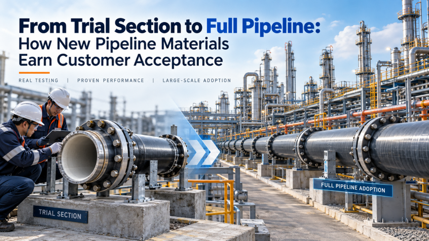
STEP 3: Establish a Trial Section
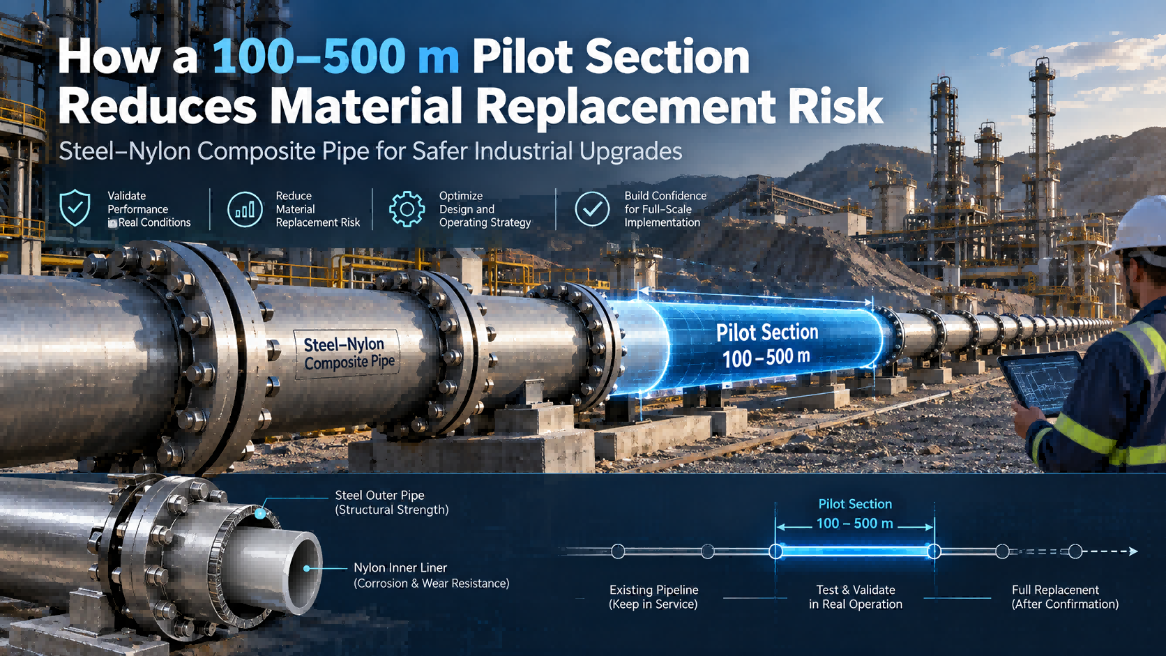
For customers using steel–nylon composite pipe for the first time, a practical approach is to install:
A 100–500 Meter Trial Section or Several Critical Fittings
Key parameters to monitor include:
-
Wall-thickness change;
-
Internal wear;
-
Connection condition;
-
Leakage;
-
Pump operating parameters.
This allows the customer to validate the material using actual field data rather than relying entirely on laboratory results.
STEP 4: Gradually Expand the Application
If the trial section performs well, the application can gradually expand from:
Elbows → Tees → Pump Discharge Sections → High-Wear Straight Pipe → Entire Pipeline
This creates a relatively controlled pathway for introducing a new pipeline material.
16. The Real Savings Come from Avoided Downtime, Not Just Lower Pipe Costs
When comparing pipeline materials, purchasing teams often begin with:
Price per meter.
For continuous-process industries, however, a more important cost is often:
Downtime Cost.
A single elbow failure can require:
Pipeline shutdown → Pump shutdown → Production interruption → System drainage → Repair → Restart.
The real costs can include:
-
Labor;
-
Spare parts;
-
Lifting equipment;
-
Loss of transported material;
-
Environmental treatment;
-
Lost production;
-
Safety risks.
Pipeline materials should therefore be evaluated not only according to:
Purchase Price
but according to:
Total Cost of Ownership (TCO).
17. Example of a Localized Upgrade Strategy
Consider a mine tailings pipeline with the following conditions:
Pipe Diameter: DN500
Operating Pressure: 2.0 MPa
Medium: High-Solids Tailings Slurry
The mine discovers that its straight pipe sections remain relatively stable, while several elbows and tees downstream of the pumps require frequent repair.
The traditional approach would be:
Replace each elbow with the same material whenever it wears through.
A more systematic strategy would be to upgrade:
-
The first section downstream of the pump;
-
90° elbows;
-
Tees;
-
High-impact reducers;
with steel–nylon composite pipes and fittings.
An inspection program could then be established at:
3 Months / 6 Months / 12 Months
and the mine could compare:
-
Wall-thickness loss;
-
Number of repairs;
-
Unplanned downtime;
-
Annual maintenance cost.
This data-driven approach can make it easier for engineering teams, procurement departments, and management to evaluate the upgrade objectively.
18. Why Is This Strategy Particularly Suitable for Mining and Chemical Plants?
Mining and chemical companies often operate extensive pipeline networks that have already been in service for many years.
Replacing all of these pipelines at once may involve:
-
Significant capital expenditure;
-
Long shutdown periods;
-
Complex construction;
-
Risk associated with introducing unfamiliar materials.
For this reason:
Localized Replacement + Progressive Upgrade
is often a more practical strategy.
It can be particularly useful in:
Mining
-
Tailings transportation;
-
Iron ore slurry;
-
Copper concentrate slurry;
-
Gold mine tailings;
-
Mine backfill slurry;
-
Concentrate transportation.
Chemical Processing
-
Brine;
-
Mother liquor;
-
Lime slurry;
-
Flue-gas desulfurization slurry;
-
Alkaline solutions;
-
High-salinity wastewater.
Oil and Gas Fields
-
High-water-cut produced fluids;
-
High-salinity produced water;
-
Gathering lines;
-
Water injection systems;
-
Sand-containing fluids.
19. The Core Value of Steel–Nylon Composite Pipe: Addressing Corrosion, Wear, and Pressure Together
The most challenging industrial pipeline environments usually do not involve a single problem.
The real challenge is when:
Corrosion + Wear + Pressure
occur simultaneously.
A slurry pipeline must withstand abrasion.
A chemical slurry pipeline may require both abrasion and corrosion resistance.
An oilfield produced-fluid line may simultaneously contain:
-
CO₂;
-
H₂S;
-
Cl⁻;
-
Solid particles;
-
Internal pressure.
Pipeline design therefore cannot focus on only one performance parameter.
The engineering logic of steel–nylon composite pipe is:
Steel for Strength
Nylon for Corrosion and Wear Resistance
The steel structure provides mechanical strength and pressure capability, while the enhanced nylon functional layer addresses the medium-contact requirements associated with corrosion and abrasion.
20. Do Not Wait for the Entire Pipeline to Fail Before Considering an Upgrade
The best time to upgrade a pipeline is usually not:
After widespread leakage has already occurred.
A better approach is to use maintenance data to identify:
-
Which elbows are replaced most frequently;
-
Which tees experience the fastest wall-thickness loss;
-
Which pump discharge sections remain under continuous severe wear;
-
Which locations are becoming new maintenance bottlenecks.
These areas can then be prioritized for localized material upgrading.
This allows pipeline management to gradually shift from:
Reactive Maintenance
toward:
Predictive Maintenance + Long-Life Pipeline Design.
Conclusion: 5% of High-Risk Pipeline Sections Can Determine the Reliability of the Entire System
The most important part of an industrial pipeline system is not always the longest straight section.
In many cases, the overall reliability of the system depends on:
-
One elbow;
-
One tee;
-
One pump discharge section;
-
One high-velocity impact zone.
These components represent only a small proportion of the total pipeline length, yet they can become the weakest links in the entire production system.
Instead of waiting for the complete pipeline to enter a replacement cycle, operators can first establish a:
Pipeline Failure Map
to identify the locations with the greatest operating risk.
For industrial transportation systems simultaneously exposed to:
Abrasion, Corrosion, Impact, and Pressure,
steel–nylon composite pipe can be evaluated first for elbows, tees, pump discharge sections, and other high-wear areas.
For many aging mining, chemical, and oilfield pipeline systems:
Localized upgrading is not merely a temporary repair strategy. It can be the most practical first step toward extending the service life of the entire pipeline system.
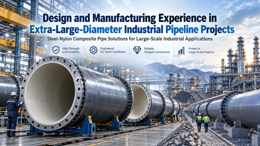
Design and Manufacturing Experience in Extra-Large-Diameter Industrial Pipeline Projects
How a 100–500 Meter Pilot Pipeline Helps Industrial Customers Reduce Material Replacement Risk